14 best io modules
I/O modules, short for Input/Output modules, are essential components in computer systems and electronic devices that facilitate communication between the central processing unit (CPU) and external devices or peripherals. These modules play a crucial role in enabling data transfer, control signals, and interaction between the computer and its surroundings. Here are some key points about I/O modules:
Function: I/O modules serve as intermediaries between the CPU and various input and output devices, such as keyboards, mice, displays, printers, storage devices, and sensors. They manage the flow of data between these devices and the CPU.
Data Transfer: I/O modules facilitate data transfer by converting data between the internal format used by the CPU and the format required by external devices. This includes translating data to and from digital, analog, or other signal types.
Types of I/O Modules:
- Input Modules: These modules are responsible for receiving data from external devices and transmitting it to the CPU. Examples include keyboard and mouse input modules.
- Output Modules: Output modules take data from the CPU and send it to external devices for actions such as displaying graphics, printing documents, or sending signals to control other hardware.
Communication Interfaces: I/O modules use various communication interfaces to connect with different types of devices. Common interfaces include USB, HDMI, Ethernet, serial ports, and parallel ports.
Buffering and Timing Control: I/O modules often include buffer memory to temporarily store data to ensure a smooth and consistent flow of information between the CPU and peripherals. Timing control circuits synchronize data transfer to maintain accuracy and reliability.
Interrupt Handling: I/O modules can generate interrupts to alert the CPU when data is ready to be processed or when specific events occur. This feature helps reduce the need for continuous polling by the CPU, conserving processing resources.
Device Drivers: Device drivers are software components that allow the operating system to communicate with I/O modules and their associated devices. They provide an interface for the OS to control and manage external devices.
Expansion Cards: In desktop computers, I/O modules are often integrated into the motherboard. However, additional I/O functionality can be added through expansion cards that plug into slots on the motherboard, such as PCI or PCIe slots.
Industrial Applications: I/O modules are widely used in industrial automation and control systems to connect sensors, actuators, and other devices to programmable logic controllers (PLCs) or industrial computers.
Customization: Some I/O modules can be customized to suit specific applications by adding or removing interfaces or by configuring them for specialized tasks.
In summary, I/O modules are crucial components in computers and electronic systems, enabling the exchange of data and control signals between the CPU and external devices.They come in various types and interfaces, catering to a wide range of applications in both consumer electronics and industrial settings.
Below you can find our editor's choice of the best io modules on the market
Electronics-Salon Pi Screw Terminal Block Breakout Module, for Raspberry Pi.
Electronics-Salon
Product description
Pi Terminal Block Breakout Module - for Raspberry Pi.
The item has been soldered and assembled, with mounting screws, standoffs and labels.
Terminal block pitch 3.5mm/0.138", wire size range 26AWG to 16AWG, strip length 5mm, screw M2 steel, pin header and cage copper.
FR-4 fiber glass PCB, dual copper layers, pads grid pitch 2.54mm/0.1", hole diameter 0.8mm.
NOTE: the item not include Raspberry Pi.
User questions & answers
| Question: | What size are the screw threads of the stand offs for mounting |
| Answer: | The standoff M2.5 L11mm |
| Question: | Is there a table available that lists pin numbers and corresponding labels, for example pin 05=scl, pin 07=io4, pin 08=txd? this would really help |
| Answer: | Hi, yes there's one, you can type on your raspberry pi "gpio readall" and it will give you a list with all the labels taht you need, hope it helps. |
| Question: | How are the pins are label on this board? Because the numbers doesn't make any sense at all |
| Answer: | I believe they are labeled based on the BCM Board configuration so in your program you need to set your board mode to BCM. Look up the PI 3 BCM board pinout and it should all make sense. |
| Question: | sorry I am totally new at this, I just got my 1st Raspberry pi yesterday. What is this product for and what uses does it have? thank you |
| Answer: | It allows you to use the wire taps on the breakout to attach wire or jumpers to connect to runs on a breadboard or directly to such things as LEDs,switches,motors or whatnot. That way you don't have to solder to the Raspberry Pi |

Waveshare Compute Module IO Board with PoE Feature Composite Breakout Board for Developing with Raspberry Pi CM3 / CM3L / CM3+ / CM3+L
Waveshare
Product description
Overview
The Compute Module PoE Board is a development board which you can plug a Raspberry Pi Compute Module into, and make use of the resources of Pi more flexibly. With the PoE (Power over Ethernet) feature, and versatile onboard peripheral interfaces, it is suitable for evaluating the Raspberry Pi compute module, also is an ideal choice for end products.
Features
Raspberry Pi GPIO header, for connecting sorts of Raspberry Pi HATs
10/100M auto-negotiation Ethernet port, with PoE enabled
4x USB ports, allows connecting more USB devices
2x CSI camera interfaces
Onboard HDMI / DSI interfaces for connecting displays
Onboard USB TO UART, for serial debugging
Cooling fan interface, auto run on power up OR controlled by IO pins
Adopts isolated SMPS (Switching Mode Power Supply)
Specifications
Power supply: micro USB port / PoE Ethernet port
PoE power input: 37V ~ 57V DC in
PoE power output: 5V 2.5A DC out
Network standard: 802.3af PoE standard
Dimensions: 114mm × 84.4mm
Mounting hole size: 3.2mm
Development Resources
Wiki : www.waveshare.com/wiki/Compute_Module_PoE_Board
- The Compute Module PoE Board is a development board which you can plug a Raspberry Pi Compute Module into, and make use of the resources of Pi more flexibly. With the PoE (Power over Ethernet) feature, and versatile onboard peripheral interfaces, it is suitable for evaluating the Raspberry Pi compute module, also is an ideal choice for end products.
- Raspberry Pi GPIO header, for connecting sorts of Raspberry Pi HATs 10/100M auto-negotiation Ethernet port, with PoE enabled 4x USB ports, allows connecting more USB devices 2x CSI camera interfaces Onboard HDMI / DSI interfaces for connecting displays
- Onboard USB TO UART, for serial debugging Cooling fan interface, auto run on power up OR controlled by IO pins Adopts isolated SMPS (Switching Mode Power Supply)
- Power supply: micro USB port / PoE Ethernet port PoE power input: 37V ~ 57V DC in PoE power output: 5V 2.5A DC out
- Network standard: 802.3af PoE standard Dimensions: 114mm × 84.4mm Mounting hole size: 3.2mm

Waveshare Compute Module IO Board Plus Development Composite Breakout Board for Developing with Raspberry Pi CM3 CM3L Various Common Use Components
Product description
Overview
The Compute Module IO Board Plus is a development board which you can plug a Raspberry Pi Compute Module into, and make use of the resources of Pi more flexibly.
It is compatible with the Compute Module IO Board V3 from the Raspberry Pi Foundation, along with various common use components.
Compute Module IO Board Plus Features
Compatible with the Compute Module IO Board V3 from the Raspberry Pi Foundation
Raspberry Pi GPIO header, for connecting sorts of Raspberry Pi HATs
connectivity, also supports shields
1-WIRE interface, for connecting single-bus devices like DS18B20
4x keys, 4x LEDs, 1x Buzzer, for I/O testing
Onboard USB HUB, allows connecting more USB devices
IR receiver, IR remote control is available
Onboard USB TO UART, for serial debugging
Sensor interface
10-bit ADC, 38KSPS, 11-ch (6-ch for interface, 5-ch for sensors)
16-bit DAC, 2-ch
Onboard RTC, one of the most common and useful functions
- The Compute Module IO Board Plus is a development board which you can plug a Raspberry Pi Compute Module into, and make use of the resources of Pi more flexibly. It is compatible with the Compute Module IO Board V3 from the Raspberry Pi Foundation, along with various common use components.
- Compatible with the Compute Module IO Board V3 from the Raspberry Pi Foundation Raspberry Pi GPIO header, for connecting sorts of Raspberry Pi HATs
- connectivity, also supports shields 1-WIRE interface, for connecting single-bus devices like DS18B20 4x keys, 4x LEDs, 1x Buzzer, for I/O testing
- Onboard USB HUB, allows connecting more USB devices IR receiver, IR remote control is available Onboard USB TO UART, for serial debugging Sensor interface
- 10-bit ADC, 38KSPS, 11-ch (6-ch for interface, 5-ch for sensors) 16-bit DAC, 2-ch Onboard RTC, one of the most common and useful functions
User questions & answers
| Question: | How many gpio's do you get |
| Answer: | Same as any Raspberry Pi. Depends on how you hook it up though. You need a device overlay to assign the GPIO pins. |
| Question: | Is this version compatible the CM3+modules |
| Answer: | Hi Dear, yes. |
| Question: | Can the board be powered via the gpio headers |
| Answer: | While it can be, the LM1117 voltage regulators don't like being backfed power and may be damaged. So if you only plan to do it that way, go ahead, but if you plan to power it more conventionally later you might want to allow for sacrificing the LDOs. |
| Question: | Can 10-bit adc, 38ksps accept 12v dc analog signal |
| Answer: | No, you must reduce or divide the 12v to a 3.3V or less signal. Use a 100 ohm resistor in series to reduce current in rush damage to the ADC input |

Compute Module 3 Development Kit Type A for Raspberry PI Include CM3 IO Board DS18B20 and IR Remote Controller The Pi in a Flexible Form Factor with 4GB eMMC Flash
WaveShare-IOT
Product description
Raspberry Pi Compute Module 3 Development Kit Type A, CM3 IO Board, DS18B20, IR Remote Controller
Overview
Since the Raspberry Pi Foundation released the Compute Module 3, you may have been watching it for some time, don't know how to get started. Now it's time to get moving. We prepare this development kit for you to evaluate the Compute Module 3 quickly, reducing your development cycle.
The key parts in this Compute Module 3 development kit includes:
Compute Module 3: Raspberry Pi 3 industrial version, the Pi in a flexible form factor, with 4GB eMMC Flash
Compute Module IO Board Plus: Extend kinds of interfaces from CM3, such as USB, HDMI, just like the regular Pi, to help evaluating
Compared to CM1, the CM3/CM3L supports more OS, like Windows 10 (the free IOT-specific version from Microsoft)
Compute Module IO Board Plus Features
Compatible with the Compute Module IO Board V3 from the Raspberry Pi Foundation
Raspberry Pi GPIO header, for connecting sorts of Raspberry Pi HATs
Arduino connectivity, also supports Arduino shields
1-WIRE interface, for connecting single-bus devices like DS18B20
4x keys, 4x LEDs, 1x Buzzer, for I/O testing
Onboard USB HUB, allows connecting more USB devices
IR receiver, IR remote control is available
Onboard USB TO UART, for serial debugging
Sensor interface
10-bit ADC, 38KSPS, 11-ch (6-ch for Arduino interface, 5-ch for sensors)
16-bit DAC, 2-ch
Onboard RTC, one of the most common and useful functions
PACKAGE CONTENT
Compute Module 3 x1
Compute Module IO Board Plus x1
DS18B20 x1
IR remote controller x1
LCD adapter x1
22PIN FFC x1
RPi Zero V1.3 Camera Cable 15cm x1
Power adapter US standard 5V/2.5A USB output x1
USB type A plug to micro B plug cable 120cm x2
Jumper Wire 4-pin to separated pins x2
Jumper Wire 2-pin 2.54-pitch 200mm x2
- With 4GB eMMC Flash and 1GB RAM Raspberry Pi 3 INDUSTRIAL version, the Pi in a flexible form factor
- Raspberry Pi GPIO header, for connecting sorts of Raspberry Pi HATs. ARDUINO header: for connecting Arduino shields
- Compute Module IO Board Plus: Extend kinds of interfaces from CM3, such as USB, HDMI, just like the regular Pi, to help evaluating
- AC Phase Control Circuit (Dimming Circuit) / Home Automation, School Projects, Work Related Projects
- 64-bit 1.2GHz quad-core ARM Cortex-A53 processor
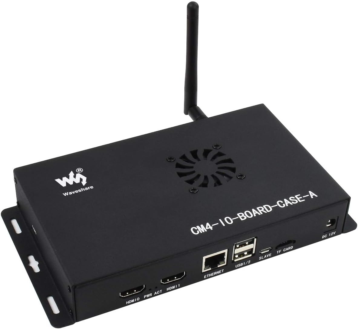
for Raspberry Pi Compute Module 4 IO Board Metal Box/Case with Cooling Fan, Mini Computer Chassis with HDMI,Power,Ethernet,USB Interface
Product description
Metal Box (A) Designed For Raspberry Pi Compute Module 4 IO Board, Comes With Cooling Fan
Features
- Metal Box Type A For CM4 IO Board
- Tailored For Compute Module 4 IO Board
- Precise Cut-Out With Clear Label
- Cooling Fan Included
- Wall Mount Support
Package Content
- Metal case (top and bottom) x1
- Screwdriver x1
- Fan-4010-PWM-12V x1
- Screws pack x1
Application Examples
Binocular Vision, PoE Powered Raspberry Pi Projects, Or Other Industrial Context
Note
- CM4, IO board, and antenna are NOT included in the product package.
- Afer-sales Service is provided within 24 hours , please contact us if you have any problem .
- The case is designed For Raspberry Pi Compute Module 4 IO Board.Mini Computer Chassis, Robust And Dust-Proof, Nice Looking
- Make It Easy To Build Your Own Raspberry Pi CM4 Mini PC
- Each Cut-Out Is Completely Aligned With The Connector
- Comes With Cooling Fan, Combined With The Airflow Vent, Better Heat Dissipation.
- Wall Mount Holes On Two Sides, Handy For Mounting
User questions & answers
| Question: | Glad to finally see an enclosure available for this io board. will a typical low profile card fit in the pcie slot using this case |
| Answer: | Yes ,a typical low profile card fit in the pcie slot using this case. |

Genuine Compute Module IO Board Plus Development Composite Breakout Board for Developing with Raspberry Pi CM3 CM3L Various Common Use Components Supports Arduino Shields
Product description
Compute Module IO Board Plus, Composite Breakout Board for Developing with Raspberry Pi CM3 / CM3L / CM3+ / CM3+L
The Compute Module IO Board Plus is a development board which you can plug a Raspberry Pi Compute Module into, and make use of the resources of Pi more flexibly. It is compatible with the Compute Module IO Board V3 from the Raspberry Pi Foundation, along with various common use components.
- Onboard USB HUB, allows connecting more USB devices IR receiver, IR remote control is available Onboard USB TO UART, for serial debugging Sensor interface
- 10-bit ADC, 38KSPS, 11-ch (6-ch for Arduino interface, 5-ch for sensors) 16-bit DAC, 2-ch Onboard RTC, one of the most common and useful functions
- Arduino connectivity, also supports Arduino shields 1-WIRE interface, for connecting single-bus devices like DS18B20 4x keys, 4x LEDs, 1x Buzzer, for I/O testing
- The Compute Module IO Board Plus is a development board which you can plug a Raspberry Pi Compute Module into, and make use of the resources of Pi more flexibly. It is compatible with the Compute Module IO Board V3 from the Raspberry Pi Foundation, along with various common use components.
- Compatible with the Compute Module IO Board V3 from the Raspberry Pi Foundation Raspberry Pi GPIO header, for connecting sorts of Raspberry Pi HATs
User questions & answers
| Question: | Does this board come with power supply |
| Answer: | No it does not come with Power Supply. Just board. |
| Question: | Are there open-source files for this to view connection details? like eagle cad |
| Answer: | All the documentation can be found on the waveshare dot com wiki including shematics. |

Compute Module IO Board with PoE Feature for Raspberry Pi Compute Module (CM3 / CM3L / CM3+ / CM3+L),Raspberry Pi GPIO Header, for Connecting Sorts of Raspberry Pi Hats
Product description
Compute Module IO Board with PoE Feature, Composite Breakout Board for Developing with Raspberry Pi CM3 / CM3L / CM3+ / CM3+L
Overview
The Compute Module PoE Board is a development board which you can plug a Raspberry Pi Compute Module into, and make use of the resources of Pi more flexibly. With the PoE (Power over Ethernet) feature, and versatile onboard peripheral interfaces, it is suitable for evaluating the Raspberry Pi compute module, also is an ideal choice for end products.
Features
Specifications
Development Resources
https://www.waveshare.com/wiki/Compute_Module_PoE_Board
Package Content
Compute Module PoE Board x1
Note: compute module in the photo is NOT included.
- Compute Module IO Board with PoE Feature, Composite Breakout Board for Developing with Raspberry Pi CM3 / CM3L / CM3+ / CM3+L
- With Raspberry Pi GPIO header, for connecting sorts of Raspberry Pi HATs. 10/100M auto-negotiation Ethernet port, with PoE enabled.
- .4x USB ports, allows connecting more USB devices. 2x CSI camera interfaces.
- Onboard HDMI / DSI interfaces for connecting displays. Onboard USB TO UART, for serial debugging. Cooling fan interface, auto run on power up OR controlled by IO pins. Adopts isolated SMPS (Switching Mode Power Supply).
- Power supply: micro USB port / PoE Ethernet port. PoE power input: 37V ~ 57V DC in. PoE power output: 5V 2.5A DC out. Network standard: 802.3af PoE standard.

waveshare Compute Module IO Board with PoE Feature Development Board for Raspberry Pi CM3 / CM3L / CM3+ / CM3+L,with Ethernet Port,USB Ports,HDMI/DSI/CSI Camera Interface
Product description
Compute Module IO Board With PoE Feature, Composite Breakout Board For Developing With Raspberry Pi CM3 / CM3L / CM3+ / CM3+L
Overview
The Compute Module PoE Board is a development board which you can plug a Raspberry Pi Compute Module into, and make use of the resources of Pi more flexibly. With the PoE (Power over Ethernet) feature, and versatile onboard peripheral interfaces, it is suitable for evaluating the Raspberry Pi compute module, also is an ideal choice for end products.
Specifications
- Power supply: micro USB port / PoE Ethernet port
- PoE power input: 37V ~ 57V DC in
- PoE power output: 5V 2.5A DC out
- Network standard: 802.3af PoE standard
- Dimensions: 114mm × 84.4mm
- Mounting hole size: 3.2mm
Development Resources
Wiki :www.waveshare.com/wiki/Compute_Module_PoE_Board?Amazon
Package Content
Compute Module PoE Board x1
Note
Compute module in the photo is NOT included.
Provide Technical Support, please contact us if you have any question
- Raspberry Pi GPIO header, for connecting sorts of Raspberry Pi HATs
- 10/100M auto-negotiation Ethernet port, with PoE enabled.4x USB ports, allows connecting more USB devices.2x CSI camera interfaces
- Onboard HDMI / DSI interfaces for connecting displays
- Onboard USB TO UART, for serial debugging
- Cooling fan interface, auto run on power up OR controlled by IO pins.Adopts isolated SMPS (Switching Mode Power Supply)
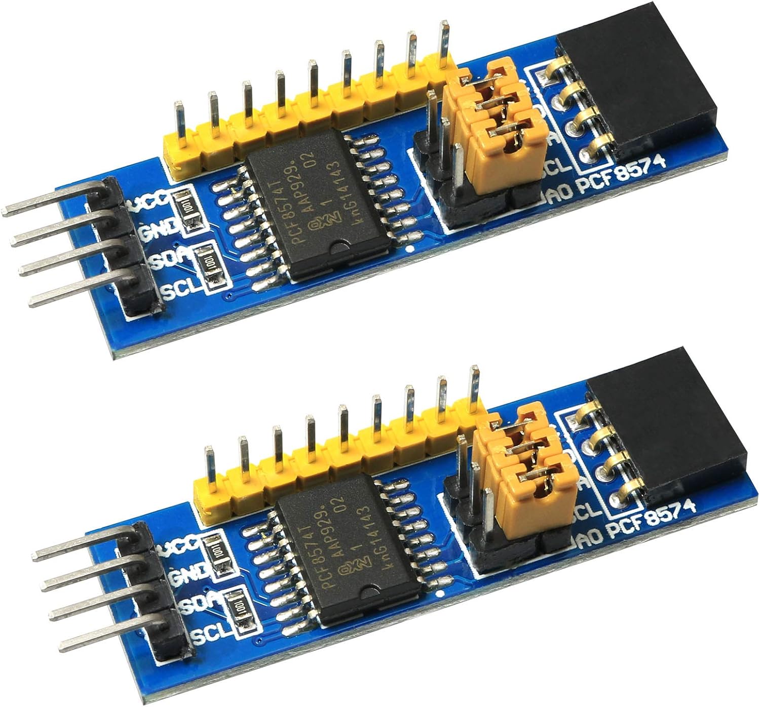
ZZHXSM 2pcs PCF8574 PCF8574T Module IO Expansion Module I/O Expansion Module I2C for I/O Resource Constraints The MCU I/O Expansion
Product description
Specification:
Type: Modular/Components and Parts
Size: 54x15mm
Frequency band: None
Interface: I2C
Plate type: Pin or row seat
Package includes: 2 x PCF8574 I/O Expansion Module
Applications: for I/O resource constraints the MCU I/O expansion.
The main resources: PCF8574, I2C interface, the 8-bit parallel.
The I/O expansion module based on I2C interface can be expanded to eight I/OS with two I/OS (up to eight PCF8574 at the same time, and 64 I/O at most)
There are two types of interface: row or pin.
Supports I2C bus cascading (multiple I2C modules can be used at the same time through pin arrangement and docking method)
- Package includes: 2 x PCF8574 I/O Expansion Module
- It can be expanded to standard interface of various development boards, I2C interface, I/O expansion module, two I/O expansibility and 8 I/O (the maximum number of PCF8574 used at the same time is expanded to 64 I/O)
- I2C serial port 8-bit parallel port, support expansion up to 8 ¡Á 8 = 64
- PCF8574 IO expansion chip with I2C interface and 8-bit parallel port output
- Suitable for various platforms, including AVR/ARM

Metal Case/Box with Cooling Fan for Raspberry Pi Compute Module 4 IO Board, Mini Computer Chassis with HDMI,Ethernet,USB,DSI Display Port, CSI Camera Port
Product description
Metal Box (A) designed for Raspberry Pi Compute Module 4 IO Board, comes with cooling fan
Features
PACKAGE CONTENT
Note: Compute Module 4 IO Board is Not included.T
Metal case (top and bottom) x1
Screwdriver x1
Fan-4010-PWM-12V x1
Screws pack x1
- This Metal Box is designed for Raspberry Pi Compute Module 4 IO Board, Mini computer chassis, robust and dust-proof, nice looking.
- Make it easy to build your own Raspberry Pi CM4 mini PC. Precise cut-out with clear label,each cut-out is completely aligned with the connector
- Comes with cooling fan, combined with the airflow vent, better heat dissipation
- Wall mount holes on two sides, handy for mounting.
- Suitable for binocular vision or Raspberry Pi applications or other industrial occasions that require PoE network port power supply

2pcs PCF8574 PCF8574T IO Expansion Board I/O Expander I2C Evaluation Develop Module
Product description
Features: I2C interface, I / O expansion module, two I / O scalability 8 I / O (up to 8 simultaneous use the PCF8574 expanded to 64 I / O) Most important feature: 1. Supports two interface types access target board: Pin or row seat, Support I2C bus cascade (by pin header row seat docking methods can be used simultaneously multiple I2C modules) Typical application: I / O resource shortage MCU I / O expansion Main resources: the PCF8574 I2C interface, 8-bit parallel Information includes: Test procedures (AVR, STM8, C8051F) Circuit schematics Related PDF data

Java Language Features: With Modules, Streams, Threads, I/O, and Lambda Expressions

Compute Module IO Board with PoE Feature Development Board Composite Breakout Board for Developing with Raspberry Pi CM3 / CM3L / CM3+ / CM3+L,Onboard 10/100M Ethernet Port,USB Ports
Product description
Compute Module IO Board With PoE Feature, Composite Breakout Board For Developing With Raspberry Pi CM3 / CM3L / CM3+ / CM3+L
Overview
The Compute Module PoE Board is a development board which you can plug a Raspberry Pi Compute Module into, and make use of the resources of Pi more flexibly. With the PoE (Power over Ethernet) feature, and versatile onboard peripheral interfaces, it is suitable for evaluating the Raspberry Pi compute module, also is an ideal choice for end products.
Specifications
- Power supply: micro USB port / PoE Ethernet port
- PoE power input: 37V ~ 57V DC in
- PoE power output: 5V 2.5A DC out
- Network standard: 802.3af PoE standard
- Dimensions: 114mm × 84.4mm
- Mounting hole size: 3.2mm
Package Content
Compute Module PoE Board x1
- Raspberry Pi GPIO header, for connecting sorts of Raspberry Pi HATs
- 10/100M auto-negotiation Ethernet port, with PoE enabled
- 4x USB ports, allows connecting more USB devices.2x CSI camera interfaces
- Onboard HDMI / DSI interfaces for connecting displays.Onboard USB TO UART, for serial debugging
- Cooling fan interface, auto run on power up OR controlled by IO pins.Adopts isolated SMPS (Switching Mode Power Supply)
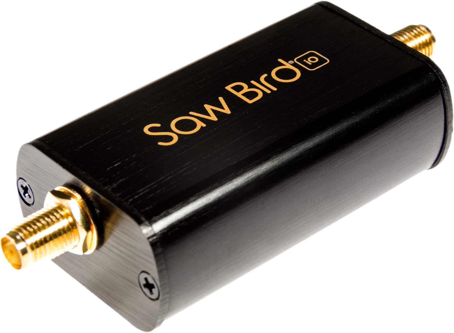
Nooelec SAWbird iO - Premium Dual Ultra-Low Noise Amplifier (LNA) & Saw Filter Module for Inmarsat Applications. 1542MHz Center Frequency
Product description
For full product details, please visit the product page at nooelec.com!
SAWbird iO is a self-contained LNA module designed for capturing L-Band signals, like Inmarsat AERO and STD-C. It has a very high attenuation outside of the 60MHz bandpass region, centered around 1.542GHz, and a minimum of 20dB of gain within the bandpass region. Nominal current draw is only 30mA.
The SAWbird series contains 2 ultra-low-noise LNAs (single package), sandwiched around a custom-designed, high-performance SAW filter centered at the frequency of interest.
Bias tee power input is 3.0V-5.0V DC.
Our recommendation for use with this LNA is the NESDR SMArTee--which contains a bias-tee capable of powering the SAWbird+ iO module with bias power--but it is compatible with many available SDRs. If you wish to use an SDR that does not have DC output to power accessories, you will also require a separate bias tee module to power this device.
- SAWbird iO is a self-contained LNA module designed for capturing L-Band signals, particularly Inmarsat AERO and STD-C
- Each module contains 2 ultra-low-noise LNAs (single package), sandwiched around a custom-designed, high-performance SAW filter centered at 1542MHz
- The amplifier must be powered through the output SMA (bias-tee) and requires only ~30mA of current
- Though compatible with most SDRs with DC (bias-tee) power, we recommend use in conjunction with NESDR SMArTee (available on Amazon, item ID B079C4S2BT)
- Includes free male SMA to male SMA adapter. Full 1 year warranty and support direct through Nooelec!
Latest Reviews
View all
Big Fish Games Pc Games
- Updated: 09.05.2023
- Read reviews
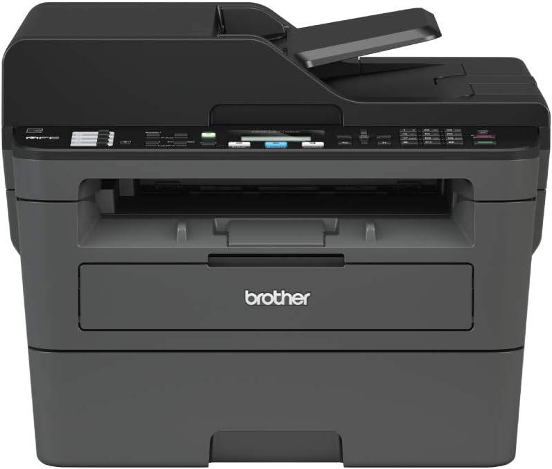
Brother Printer
- Updated: 17.06.2023
- Read reviews
Strung Lacrosse Heads
- Updated: 08.03.2023
- Read reviews

Baby Monthly Box
- Updated: 27.04.2023
- Read reviews

Kyocera Printers
- Updated: 28.01.2023
- Read reviews