14 best pcb prototyping
PCB (Printed Circuit Board) prototyping is a crucial process in electronics design and manufacturing. It involves the creation of prototype circuit boards to test and validate electronic designs before mass production. Here's what you need to know about PCB prototyping:
Prototyping Boards: PCB prototyping boards, also known as protoboard or breadboard, are flat boards with an array of holes or pads that allow electronic components to be easily connected and tested. These boards come in various sizes and configurations.
Design Validation: PCB prototyping is primarily used for design validation and testing. Engineers and electronics enthusiasts use these boards to build and test electronic circuits to ensure they function as intended before moving to mass production.
Component Placement: Components like resistors, capacitors, integrated circuits, and connectors are inserted into the holes or soldered onto the pads on the prototyping board. This allows for easy experimentation and modification of the circuit.
Wiring: Conductive traces or wires are used to connect the components on the prototyping board, replicating the connections that would be made on a final PCB. These connections can be made using soldering, wire jumpers, or specialized connectors.
Testing and Iteration: Once the components are connected on the prototyping board, the circuit can be powered up and tested. Any issues or necessary improvements can be identified and addressed through iterations of the design.
Quick Turnaround: PCB prototyping offers a relatively quick turnaround compared to the production of custom PCBs. This allows for rapid design refinement and troubleshooting.
Use Cases: PCB prototyping is commonly used in various fields, including electronics engineering, product development, research and development, and hobbyist projects. It's an essential step in the creation of electronic devices, from simple gadgets to complex systems.
Prototyping Methods: There are different methods for PCB prototyping, including traditional perfboard or stripboard, which involves manually wiring components, and more advanced methods like using solderless breadboards or custom-made prototype PCBs.
Custom Prototyping PCBs: In some cases, custom PCBs designed specifically for prototyping are used.These boards often feature a grid of holes or pads with labels for easy component placement and routing.
Transition to Production: Once the prototype is successfully tested and refined, the design can be transitioned to a final production PCB for mass manufacturing. The prototype serves as a critical step in ensuring the final product's reliability.
In summary, PCB prototyping is a fundamental step in electronics design and development. It involves the creation of prototype circuit boards for testing and validation purposes, allowing engineers and designers to refine their electronic designs before moving on to mass production. This iterative process is essential for ensuring the functionality and reliability of electronic devices.
Below you can find our editor's choice of the best pcb prototyping on the market
ELEGOO 32 Pcs Double Sided PCB Board Prototype Kit for DIY Soldering with 5 Sizes Compatible with Arduino Kits
ELEGOO
- ★32 pieces double sided PCB prototype boards well packed in a plastic tray which is very easy to store and take out
- ★5 different size boards to meet your demands when designing your own Arduino kits, electronic experiments and DIY projects
- ★4 mounting holes at the corners of the board are very convenient for installing them together.
- ★Pre-tinned plated holes on the board make it very handy to solder components and sensors for your projects
- ★High quality of durable glass fiber –FR4 material with 1.6mm thickness makes a very solid and sturdy prototype circuit board
User questions & answers
| Question: | what is the max volts/watts/current that can be passed through the board |
| Answer: | As long as your bed frame has holes in it this headboard should work. It has several different holes, so you can customize how high or low the padded back is. I have mine attached to a basic Hollywood frame. It does NOT come with the screws to attach it though. You will have to supply those. |
| Question: | Can you cut the boards apart? That is, one board cut into 3 pieces for three independent projects |
| Answer: | I attached the headboard directly to the wall. Looks great! |
| Question: | Will M2 size standoffs fit in these mounting holes? They measure very close to 2mm |
| Answer: | No. For mine, I bought 4 sets of bolt, nut and washer from Home depot. Carriage bolt 5/6 x 1-1/2. Code AHA. Nut: ABC, washer: ABB. |
| Question: | Are electrical connections made between holes in a pattern similar to those on a solderless breadboard? Or is each hole electrically isolated |
| Answer: | I have no idea, but we have had this bed frame for 2 months, it is in my daughters room , she weighs 30lbs, and I or my husband sleep in the bed with her so 230lbs it holds. Both my kids jump on it all the time and it has held up great! |
Product features
Elegoo Double Sided Prototype Board
Product Specification:
Selection of Multi-Sized Proto Boards
32 pieces double-sided prototype boards of 5 different size to meet your demands when designing your own Arduino kits, electronic experiments and DIY projects.
Solid Quality and Great Value
High quality of durable glass fiber -FR4 material with 1.6mm thickness makes a very solid and sturdy prototype circuit board.
Pre-tinned Holes for Handy Soldering
Pre-tinned plated holes on the board make it very handy to solder components and sensors for your projects.
Compact and Elegant Packaging
ELEGOO double-sided perfboard comes with a elegant package which contains all the 32 pcs boards in a plastic tray for easy storage.
Package List
- 6pcs 4X6CM double-sided PCB board with 280 holes
- 10pcs 3X7CM double-sided PCB board with 240 holes
- 7pcs 5X7CM double-sided PCB board with 432 holes
- 7pcs 2 X 8CM double-sided PCB board with 168 holes
- 2pcs 7 X 9CM double-sided PCB board with 806 holes
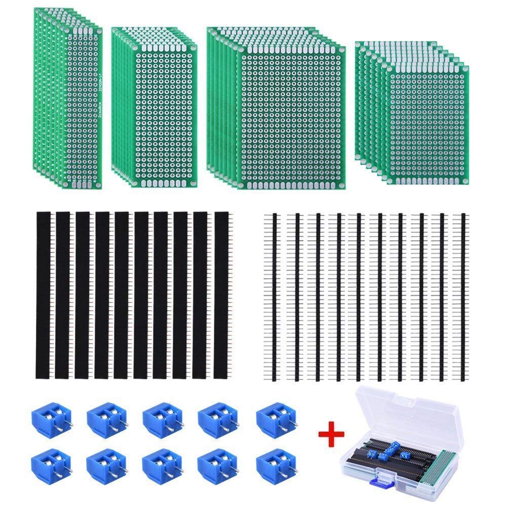
AUSTOR 30 Pcs Double Sided PCB Board Kit 4 Sizes Circuit Board with 20 Pcs 40 Pin 2.54mm Header Connector for DIY(Bonus: 10 Pcs Screw Terminal Blocks)
AUSTOR
Product description
AUSTOR 30 Pcs Double Sided PCB Board Prototype with 20 Pcs Male and Female Header Connector and 10 Pcs Screw Terminal Blocks
PCB Board
30 Pieces in 4 different sizes, a good assortment to meet your design demands such as electronic experiments and DIY projects.
Easy to use: pre-tinned plated holes on the board make it very handy to solder components and sensors for your projects.
Easy installation: 4 mounting holes at the corners of the board are very convenient for installing them together.
Material: high quality glass fiber FR4
Hole-pitch: 2.54 mm
Header Connector
Pitch: 2.54mm, number of pins: 40pin.
Type of row: single row, type of connector: straight.
Great tool for Arduino proto shield.
Screw Terminal Block
Pitch: 5.08mm, 5.08-301-2P
Rated voltage: 300V, rated current: 16A
Package include
2x8cm Prototype PCB universal board * 8
3x7cm Prototype PCB universal board * 8
4x6cm Prototype PCB universal board * 7
5x7cm Prototype PCB universal board * 7
40Pin male header connector * 10
40Pin female header connector * 10
Screw terminal blocks * 10
Free plastic box * 1
User questions & answers
| Question: | Can someone tell me the diameter of the fixatives four holes in each corners are? Sorry if not really clear but french is my native language |
| Answer: | I measured my "mounting holes" and they are 0.083 inches (2.108 mm) in diameter. I believe a M2 screw will fit tightly, but I have not tested this. |
| Question: | Do all the pieces fit in the included case |
| Answer: | They come in the included case already. |
| Question: | The rated voltage is 300v, while the rated current is 16a for a total of 4800 watts. does this mean i can use it on a 120v 30a circuit(3600 watts |
| Answer: | This is a complicated question. **Use answer at your own risk, they are for guidance only**. So - Watts is the amount of heat and work that something generates. The board hole liners and pads have minimal resistance so the heat produced will be minimal and of course the board does not do any work. Watts really isn't something that you should consider and you are not using it in the right context. The rating of volts on the board is the di-electric breakdown or more simply the insulation between pads. The board should easily keep the pads from shorting out as it comes out of the package. You could change this if you do something like sloppy soldering, poor wiring, or spill your coke on it. Current capacity is dictated by the amount of metal used on the pads and the hole linings. The more metal, the more current. Each hole only has enough metal to safely carry 16a. Keep in mind that current has to pass "through" the board hole (i.e. top to bottom of the hole or from one side of the pad to the other) for this to be meaningful. If you are only using one side then current isn't passing through the holes. You need to size the conductor connecting the holes properly. Something that draws 30 amps at 120v is an odd specification. Usually anything above 20 AMPs moves to 220v or greater. I would not use a proto board to directly conduct 30 AMPS. I would isolate the 30 AMPS to a module that is built for whatever you are doing. Uses the proto board to build the control logic that feeds the 30 AMP module. Good Luck1 |

ALLDREI 100 Pcs Double Sided PCB Board Prototype Kit for DIY Soldering Compatible with Arduino Kits
AD-PCB-01
Product description
Components Features:
PCB Board features and info:
- 10 pcs 2 x 8 cm (168 solder points) with a matrix of 6 by 28 Plated Through Hole (PTH)
- 10 pcs 3 x 7 cm (240 solder points) with a matrix of 10 by 24 PTH
- 5 pcs 4 x 6 cm (280 solder points) matrix of 14 by 20 PTH
- 5 pcs 5 x 7 cm (432 solder points) matrix of 18 by 24 PTH
★ ★ Header Sockets
- 10 pcs 1 x 40 Pin Male Header Pin
- 10 pcs 1 x 40 Pin Female Header Pin
- 10 pcs 1 x 40 Pin Right Angle Male Header Pin
Pitch 0.1'/2.54mm; pin length 11.5mm / 0.45';
★ ★ Jumper Caps
- 30 pcs Jumper caps
★ ★ Terminal Blocks
- 5 pcs 2 Pole Terminal, (2.54-2P)
- 5 pcs 3 Pole Terminal, (2.54-3P)
★ Electrical Specification
Rated Voltage: 150V/AC; Rated current: 6A; Contact Resistance: 20m Ohm MAX; Insulation; Resistance: 5000M Ohm/1000V; Dielectric Strength: 1250V/1 min
★ Mechanical Specification
Temp range: -40F ~ +105C; Torque: 0.1 Nm; Wire range: 26~18AWG; MAX Soldering: +250C for 5 Sec; Strip length: 4.5mm; Pitch 0.1'/2.54mm Terminal blocks; Poles: 2P, 3P
★ Part and Material
Screw: M1.5 Steel Zinc plated; Wire guard: Brass, Ni plated; Pin header: Brass, Tin plated; Housing: PA66, UL94V-0
- PCB Board: 30 pieces double sided PCB prototype boards in 4 sizes, Double sided board with plated-thru holes allows components to be easily soldered to either side of the board
- 3 Types of Header Connector: 10 pieces 40 pin male header, 10 pieces 40 pin pitch right angle male headers, 10 pieces 40 pin female header; pitch: 0.1'/2.54mm, single row and straight connector
- 2 Types of Terminal Blocks: 5 pieces 2.54-308-2P and 5 pieces 2.54-308-3P; Pitch: 0.1'/2.54mm
- Jumper caps: 30 pieces standard 2.54mm pin spacing circuit board jumper cap
- 100 % SATISFACTION GUARANTED: General purpose prototyping circuit board for analog and digital use; With pre-tinned plated holes; Extra accessories to make life easy for you (Screw Terminal Block and Headers)

HiLetgo 20pcs 5x7cm Bakelite DIY Prototype Board PCB 57cm Universal Breadboard Test Prototype Boards for Arduino DIY Electronics Experiments
8 years and up
Product description
20PCS 5*7CM Bakelite Prototyping Boards Solder Finished Prototype PCB Board
High-quality bakelite materials
Flat surface and all the holes are in the middle
Material: 94HB Bakelite Board
Holes quantity: 432
Thickness: 1.2MM
Dimension: 5*7CM
Diameter of the hole: 1.0mm appx
Hole space: 2.54mm
Package Include:
20* 5*7CM Bakelite Prototyping Board DIY Kit
- DIY Prototype
- PCB Universal Board
- High-quality bakelite materials
- Flat surface and all the holes are in the middle
- Material: 94HB Bakelite Prototyping Board
User questions & answers
| Question: | What is the pin spacing |
| Answer: | Normal: 0.1 inch. |
| Question: | is double sided or sigle sided |
| Answer: | Single. |
| Question: | Can th boards be cut? If so what would work on them, a jewler's saw or hobby knife? Also how are the circuits connected-little puddles of solder |
| Answer: | Yes, they can be cut. I use a power jig saw with a very fine toothed blade. The blade tension must be quite high and you must feed the materiel slowly. A craft kmnife would work but yo shoule exoect some "chipping at the edges. |
| Question: | Are any rows of holes connected like a typical breadboard, or is it just a bunch of individual stand-alone holes |
| Answer: | Stand-alone holes. One positive thing I noticed though was the edge of the holes were laced with metal, which made soldering really simple. But yeah, you would need to connect the holes together in some manner. |

KeeYees 70pcs Universal PCB Board Kit, Including 7 Sizes Double Sided PCB Prototype Boards, 2.54mm 40 Pin Male Female Header Connector and 5mm 2 Pin / 3 Pin Screw Terminal Block
Product description
PCB Board
Dimension: 2x8 / 3x7 / 4x6 / 5x7 / 7x9 / 8x12 / 9x15CM
Thickness: about 1.6mm
Material: Glass fiber FR4
Color: Green basic, silver hole
Pitch: 2.54 mm / 0.1 inch
Diameter of the Hole: 1 mm/ 0.04 inch
Pin Header Connector
Type: Male and Female
Pin number: 40
Pitch: 2.54 mm
Type of Row: Single Row
Type of connection: straight
Screw Terminal Block
Pin number: 2 and 3
Pitch: 5mm
Rated voltage: 300V, rated current: 16A.
For wire size: 14-22AWG
Colour blue
Package includes
5pcs 2x8CM Prototype Board
5pcs 3x7CM Prototype Board
5pcs 4x6CM Prototype Board
5pcs 5x7CM Prototype Board
2pcs 7x9CM Prototype Board
2pcs 8x12CM Prototype Board
1pc 9x15CM Prototype Board
15pcs 40 Pin Female Header Connector
15pcs 40 Pin Male Header Connector
10pcs 2 Pin Screw Terminal Block
5pcs 3 Pin Screw Terminal Block
KeeYees: Best choice in various Electronic Modules & Components, DIY Parts and Tools to
support your work and design challenges from Home, School to Industrial applications!
- High cost performance PCB kit: 25pcs PCB Boards in 7 different sizes & 30pcs Pin Header & 15pcs Screw Terminal Block, just one purchase. Ideal for your DIY projects.
- PCB Board: 5pcs 2x8cm, 5pcs 3x7cm, 5pcs 4x6cm, 5pcs 5x7cm, 2pcs 7x9cm, 2pcs 8x12cm, 1pc 9x15cm, which allow to adapt to your different components.
- Pin Header: 15pcs female header, 15pcs male header; 40 pin with 2.54mm pitch.
- Screw Terminal Block: 10 x 2 pin, 5 x 3 pin, 5mm pitch.
User questions & answers
| Question: | Do those terminal screw block fit in the boards to be doldered in |
| Answer: | Some do. I've bought blue blocks that fit great. I have bought green blocks that are bigger than the holes in the pc board and need filing to fit. It depends on the blocks. The holes in the pc board are standard size for all the other electronic parts I've used. |

ElectroCookie Mini PCB Prototype Board Solderable Breadboard for DIY Electronics, Compatible for Mini Arduino Soldering Projects, Gold-Plated (6 Pack, Multicolor)
Product description
Brand : ElectroCookie
PCB type: Double-sided
Surface finish: Gold plated to prevent oxidation
Color: Multicolor
Dimensions: 2"x1.5" (50.8mm x 38.1mm)
Through hole diameter: 0.047" (1.2mm)
Mounting holes: M3 (Ø3.2mm) & M2 (Ø2.2mm)
Trace width: 0.04" (1mm)
- Useful in transferring breadboarded prototypes to reliable and permanent circuits
- 6 multicolor mini PCBs for small scale prototyping
- Applicable to various DIP-type components
- Gold plated finish to prevent oxidation, and all holes are through-plated for mounting strength
- Lead free and RoHS compliant, longer shelf life
User questions & answers
| Question: | What is the trace thickness or better still, what is the current carrying capacity of the traces |
| Answer: | I’ve hit three continuous amps so far with no problems. |
| Question: | Any listings here on Amazon for one-color packs |
| Answer: | There are some beautiful black ones with gold plating available |
| Question: | Is it just me, or does the exposed copper between holes on the reverse side make it hard to keep the solder to one hole? Or does this not matter |
| Answer: | There are 5 holes connected together by a copper trace. Note that you will usually insert the component leads through the board from the ElectroCookie label side. A fine tipped soldering iron will help to avoid "Glopping" too much solder. You DO want to avoid bridging, or having solder cross the non-solder areas onto other rows of holes. You might want to try practice soldering a board with pieces of wire- it will teach you some valuable skills in a hurry! Hope this helps! |
| Question: | What is the distance between rows E & F |
| Answer: | 7.62 (2.54*3) |

Chanzon 20 Pcs Double Sided PCB Board (4 Sizes - 2X8 3X7 4X6 5X7) Tinned Through Holes FR4 Prototype Kit Printed Circuit Universal Perfboard for DIY Soldering Project Compatible with Arduino Kits
CHANZON

Chanzon 34 Pcs Double Sided PCB Board Tinned Through Holes (5 Sizes 2X8 3X7 4X6 5X7 7x9) Prototype Kit FR4 Printed Universal Circuit Perfboard for DIY Soldering Project Compatible with Arduino Kits
CHANZON

Treedix 3 pcs Solderable BreadBoard Split Design Universal Board PCB Prototype Shield Board Double Sided Tinned Gold Plated Holes Compatible with Arduino Kit Raspberry Pi Prototyping and Testing
Product description
Specification:
Board Material: Glass Fiber FR4
Color: Blue, Gold
Hole pitch: 2.54mm
Hole diameter: 1mm
Thickness: 1.5mm
Size: 161.9 x 70 mm / 6.37 x 2.75 inch
Extension Clips: Yes (Can extend with other boards)
Input voltage: 6.5-12V (DC) or USB power supply
Output voltage: 3.3V/5V (Switchable)
Maximum output current: <700 mA
1440 tie-points total: IC-circuit area and power rails area
Packages Included:
3 x 1440 tie-points Solderable Breadboard ( Split design )
( One piece of 1440 tie-points Solderable Breadboard can be splited into three pieces of 480 tie-points Solderable Breadboard)
- Split design can turn one piece into three smaller pieces, which is easy for you to expand your projects. The features of this board is that you don't have to insert the pins of components and kits in the group of holes. Components and kits can be mounted variously on your will.
- Used for electronic experiments and point-to-point DIY soldering projects, can be expandable with pin header and female header, designing your own Arduino kits. The Breadboard Kit is convenient for the prototypes and circuit design experiment and other DIY projects. Perfect for Arduino, Raspberry Pi, and other programming boards.
- Standard IC spacing 2.54MM hole plated through among the pad can be perfectly working with 3mm&5mm LED Diode kit, Electrolytic Capacitor kit, Monolithic Ceramic Capacitor kit, Resistor kit, etc.
- Electroless Nickel Gold finished prevent the copper on PCB from being oxidized and corroded and is good for soldering and touching. To be your friendly companion on your Arduino journey.
- Made of glass fiber FR-4 material, having the features of high heat resistance, corrosion resistance, mechanical strength, insulation.

ZIIDOO 25 PCS Copper Perfboard Paper Composite PCB Boards Universal Breadboard Single Sided Printed Circuit Board for Prototyping and Electronic Making
zido tech
- You will get 25 PCS copper perfboards 5CM by 7CM sized .
- Solderable on front sides so you can make it easier to follow your circuits. Perfectly flat, all holes drilled clean.
- The glass fiber PCB boards are thick and sturdy and they do not melt when solder is applied.
- High-quality bakelite materials,flat surface and all the holes are in the middle.
- This is a great buy for kids and adults learning about electronics and starting to develop their electronic and soldering skills.
User questions & answers
| Question: | Is it possible to cut these into smaller sections with a knife or a hobby saw |
| Answer: | Hello Without the aid of tools, the PCB board can be divided into different cells by hand, |
Product features
ZIIDOO 25 PCS Copper Perfboard Paper Composite PCB Boards
25Pcs Copper Perfboard Paper Composite PCB Boards 5CM by 7CM sized .
Packed with Moisture Protecting Bag to Prevent Copper Rust.

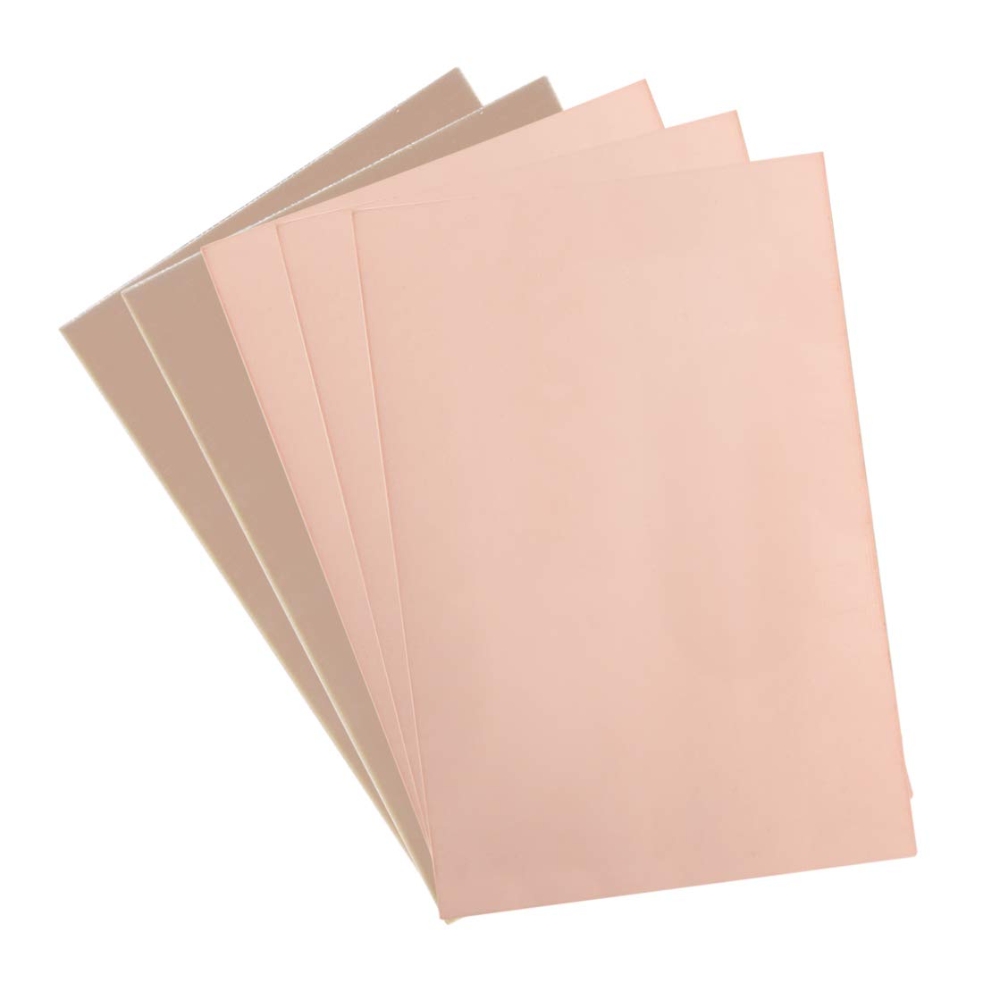
uxcell Double-Sided Copper Clad Laminate PCB Circuit Board, FR4 200x200mm 7.87x7.87 inch, 1.5mm Thickness DIY Prototyping PCB Board, Name Board, 10pcs
uxcell
- 【Material】 Material: FR-4 Glass Fiber, Copper; Layers: Double-sided.
- 【Size】Dimension: 200x200mm/ 7.87x7.87 inch(L*W); Thickness : approx. 1.5mm.
- 【Applications】Great for making PCB Circuit Board, Models. Widely used in product development, DIY experiments, maintenance, production, etc.
- 【Stable】Mechanically supports and electrically connects electronic components using conductive tracks, pads and other features etched from copper sheets laminated onto a non-conductive substrate.
- 【Note】The product may be slightly scratched or dirty during transportation, which will not affect its use.
Product features
Copper Clad Board
Material: FR-4 Glass Fiber, Copper
Layers: Double-Sided
Applications
Widely used in television, radio, computer, mobile communications, and other electronic products.
Features
- High mechanical and dielectric properties
- High flatness, excellent bending strength at high temperature
- Good heat resistance and moisture resistance
- Low thermal conductivity, excellent processing performance
PCB Circuit Board Making
Name Board
DIY Experiments

uxcell Double-Sided Copper Clad Laminate PCB Circuit Board, FR4 400x300mm 15.75x11.81 inch, 1.6mm Thickness DIY Prototyping PCB Board, Name Board
uxcell
- 【Material】 Material: FR-4 Glass Fiber, Copper; Layers: Double-sided.
- 【Size】Dimension: 400x300mm/ 15.75x11.81 inch(L*W); Thickness : approx. 1.6mm.
- 【Applications】Great for making PCB Circuit Board, Models. Widely used in product development, DIY experiments, maintenance, production, etc.
- 【Stable】Mechanically supports and electrically connects electronic components using conductive tracks, pads and other features etched from copper sheets laminated onto a non-conductive substrate.
- 【Note】The product may be slightly scratched or dirty during transportation, which will not affect its use.
Product features
Copper Clad Board
Material: FR-4 Glass Fiber, Copper
Layers: Double-Sided
Applications
Widely used in television, radio, computer, mobile communications, and other electronic products.
Features
- High mechanical and dielectric properties
- High flatness, excellent bending strength at high temperature
- Good heat resistance and moisture resistance
- Low thermal conductivity, excellent processing performance
PCB Circuit Board Making
Name Board
DIY Experiments

SIQUK 30 Pcs PCB Board with 60 Pcs Led Diodes 20 Pcs Header Connector and 40 Pcs Jumper Wire 10 Pcs Screw Terminal Block and 15 Pcs Tactile Cap Switch
SIQUK
Product description
SIQUK 175 Pices Prototype PCB Board Kit
PCB Board
Material: high quality glass fiber FR4
Hole-pitch: 2.54 mm
Quantity: 30 pieces
Size: 2*8cm, 3*7cm, 4*6cm, 5*7cm
LED Diodes
View angle: 15-30 Degree
Head type: round
3mm Led forward voltage: red 2.1-2.4V; yellow 1.8-2.4V; white/blue/green 3.0-3.2V
Max. current: 20 mA
Header Connector
Pitch: 2.54mm, number of pins: 40pin.
Type of row: single row, type of connector: straight.
Screw Terminal Block
Pitch: 5.08mm, 5.08-301-2P, 5.08-301-3P
Rated voltage: 300V, rated current: 16A
Dupont wire
Length: about 20cm
Size: 0.127mm, single root
Pitch: 2.54mm headers and sockets
Tactile Cap Switch
Tactile switch with button cap
Package include
2x8cm Prototype PCB universal board * 10
3x7cm Prototype PCB universal board * 10
4x6cm Prototype PCB universal board * 5
5x7cm Prototype PCB universal board * 5
40-Pin male header connector * 10
40-Pin pitch right angle male headers * 10
3mm Light emitting diodes * 60
Female to female jumper wire * 40
5.08-301-2P * 5
5.08-301-3P * 5
Tactile cap switch * 15
Free plastic box * 1
User questions & answers
| Question: | Are the led diodes bright |
| Answer: | They are not the super bright type if that is what you are asking. Think standard old-school Radio Shack LEDs you used to buy, plenty bright for standard electronics use. |
uxcell Single-Sided Copper Clad Laminate PCB Circuit Board, FR4 150x100mm 5.91x3.94 inch, 1.2mm Thickness DIY Prototyping PCB Board, Name Board, 5pcs
uxcell
- 【Material】 Material: FR-4 Glass Fiber, Copper; Layers: Single-sided.
- 【Size】Dimension: 150x100mm/ 5.91x3.94 inch(L*W); Thickness : approx. 1.2mm.
- 【Applications】Great for making PCB Circuit Board, Models. Widely used in product development, DIY experiments, maintenance, production, etc.
- 【Stable】Mechanically supports and electrically connects electronic components using conductive tracks, pads and other features etched from copper sheets laminated onto a non-conductive substrate.
- 【Note】The product may be slightly scratched or dirty during transportation, which will not affect its use.
User questions & answers
| Question: | How many pcs in the pack |
| Answer: | I had 5 copper clads |
Product features
Copper Clad Board
Material: FR-4 Glass Fiber, Copper
Layers: Single-Sided
Applications
Widely used in television, radio, computer, mobile communications, and other electronic products.
Features
- High mechanical and dielectric properties
- High flatness, excellent bending strength at high temperature
- Good heat resistance and moisture resistance
- Low thermal conductivity, excellent processing performance
PCB Circuit Board Making
Name Board
DIY Experiments
Latest Reviews
View all
Office Star Glass Desks
- Updated: 07.03.2023
- Read reviews

Rca Headphones Under 40 Dollars
- Updated: 01.07.2023
- Read reviews

Gas Hot Plate Portable
- Updated: 10.06.2023
- Read reviews
Greenland Home Fashions Bedspreads
- Updated: 05.06.2023
- Read reviews
Irobot Dealers
- Updated: 21.07.2023
- Read reviews