14 best controller for arduinos
A controller for Arduinos typically refers to a hardware device or circuit that interfaces with an Arduino microcontroller to provide additional functionality or control over various optoelectronic and industrial applications. Arduinos are widely used in industrial and scientific settings for tasks such as data acquisition, automation, and control.
The term "controller for Arduinos" can encompass various components and features, depending on the specific application. Some common elements associated with controllers for Arduinos in these contexts include:
Sensors and Detectors: Controllers can be equipped with sensors such as photodetectors, thermistors, or accelerometers to collect data from the environment or machines.
Actuators: These controllers can also drive various types of actuators like motors, relays, or solenoids to control physical processes or devices.
Communication Interfaces: Many controllers for Arduinos include communication interfaces like UART, I2C, SPI, or wireless (e.g., Bluetooth or Wi-Fi) to exchange data with other devices or systems.
Processing Power: Depending on the complexity of the task, controllers may have additional processing capabilities beyond what the Arduino microcontroller itself provides.
Power Management: They often include power management features to ensure the safe operation of connected devices.
Customization: Controllers for Arduinos are designed to be customizable, allowing users to adapt them to their specific industrial or optoelectronic requirements.
These controllers are valuable tools for engineers and hobbyists working on a wide range of projects, from automated industrial processes to scientific experiments involving sensors and actuators.They allow for more advanced and tailored control and data acquisition compared to using the Arduino board alone.
Below you can find our editor's choice of the best controller for arduinos on the market
DC Motor Driver, DROK L298 Dual H Bridge Motor Speed Controller DC 6.5V-27V 7A PWM Motor Regulator Board 12V 24V Electric Motor Control Module Industrial 160W with Optocoupler Isolation
Product description
Parameters:
1. Power supply voltage 6.5V-27V, the power cannot be reversed or over 27V, or may burn the module, it is recommended connecting in series 15A fuse in the power input.
2. Dual motor interface, each rated output current 7A, peak current 50A, the motor interface cannot short-circuit, it is recommended connecting in series 15A fuse.
3. The enable signal and forward and reverse control signal control voltage 3-6.5V.
4. Enable signal terminal (ENA) input PWM can regulate speed, PWM frequency range 0-10KHZ, PWM minimum pulse width 10us.
5. Product dimension: 55x55x16mm
6. Installation hole diameter: 3mm, noted to prevent short circuit when install the reverse side, you can add insulation pad or copper column to raise the circuit board
Parameters matched:
Motors with rated voltage 24V, identification of rated power 115W or below, and motors with identification of rated current 7A can full work for a long time.
Note:
1. Drive power cannot be reversed, it is recommended connecting in series 15A fuse in the power interface, the voltage should be between 6.5 - 27V. If over voltage, it may burn the drive module if power on.
2. It is recommended that the rated output current of the power supply be more than 2 times, in case the power supply voltage cannot reach the required input voltage of the motor when it is started, which may cause pause of the drive module for under voltage protection.
3. Motor interface cannot be short-circuit, or may burn the drive module, it is recommended connecting in series 10A fuse in the motor interface.
Package Including:
1x DC Motor Driver Board
- DROK DC motor driver input voltage range is DC 6.5V-27V, can be input DC 12V or 24V, rated output current of each port is 7A, total output power is 160W.
- STRONG DRIVE: the motor controller board adopts dual H bridge, can drive two DC motors at the same time.
- FORWARD and REVSERSELY ROTATE: the IN1, IN2/IN3, IN4 port can control forward or reverse motor rotation.
- PWM SPEED CONTROL: enable signal terminal (ENA) input PWM can regulate speed, PWM frequency range 0-10KHZ.
- UNDER VOLTAGE PROTECTION: the motor driver module is with under voltage protection to prevent instantaneous large current from damaging the module.
User questions & answers
| Question: | Could this module be used for a 12v 80ma no-load current motor? i don't think the regular l298n 2a module will supply the current needed |
| Answer: | The real question is what is the current draw when your motor is under load, because that’s when current will spike. Make sure that is safely below 7A. 80mA would be no problem. |
| Question: | The manufacturer says it needs, requires, must have a heat sink. so why did anyone manufacture it without a component that it absolutely needs |
| Answer: | I have used this board with and without heatsinks to drive NEMA 23 stepper motors at 1.5-2A, and haven't any significant heating in either case. |
| Question: | How am I supposed to have a separate ground for the motor with a single PS |
| Answer: | The polarity of the single power supply applied to the motor through the DROK is reversed by the DROK to reverse the direction of the motor if so controlled by the DROK. If the motor shares a common ground with the single power supply, there will be a short circuit through the DROK when the motor is commanded in the reverse direction. It is critical that neither motor power lead is referenced to the single power supply applied to the DROK input. |
| Question: | Can this be used to slowly increase the voltage in a power wheels type car? Wanting to increase voltage over time from 12-24v |
| Answer: | You can increase the average voltage overtime. Basically you need a 24V supply. And then you can pwm from 50% to 100% of whatever the range is. |

Arduino Shield Expansion Board 9-12V with 4 Channels Motors 9 Channels Servos Ports with PS2 Joystick Remote Control for Mecanum Wheel Robot Arm
Product description
Package included:
1pcs handle controller
1pcs receiver
1pcs adapter
1pcs 4 channel motor driver board
1pcs MEGA 2560
1pcs USB cable
4pcs motor wires
- The motor drive board adopt imported TB6612 driver chip, reserve wifi/bluetooth/handle interface.
- The Arduino controller can control the mecanum wheel robot with speed encoder, we offer the source code.
- You learn more about how Mecanum Wheels work and how they can improve your robot's maneuverability.
- You can develop it secondly, since It also has servos, sensor interface, you can use it to control the robot arm or mini self-driving robotic car.
- Package included: 1pcs handle controller, 1pcs receiver, 1pcs adapter, 1pcs 4 channel motor driver board, 1pcs MEGA 2560, 1pcs USB cable, 4pcs motor wires.
User questions & answers
| Question: | Is there any documentation and code available for this item |
| Answer: | Yes, we offer the GitHub link. |
| Question: | Can you provide wiring diagram and GitHub firmware link? This will be used by high school students and they need a manual or good documentation |
| Answer: | You can directly ask us seller for the manual. |
| Question: | Where do I find the link for schematic and programming |
| Answer: | You can directly ask us seller. |
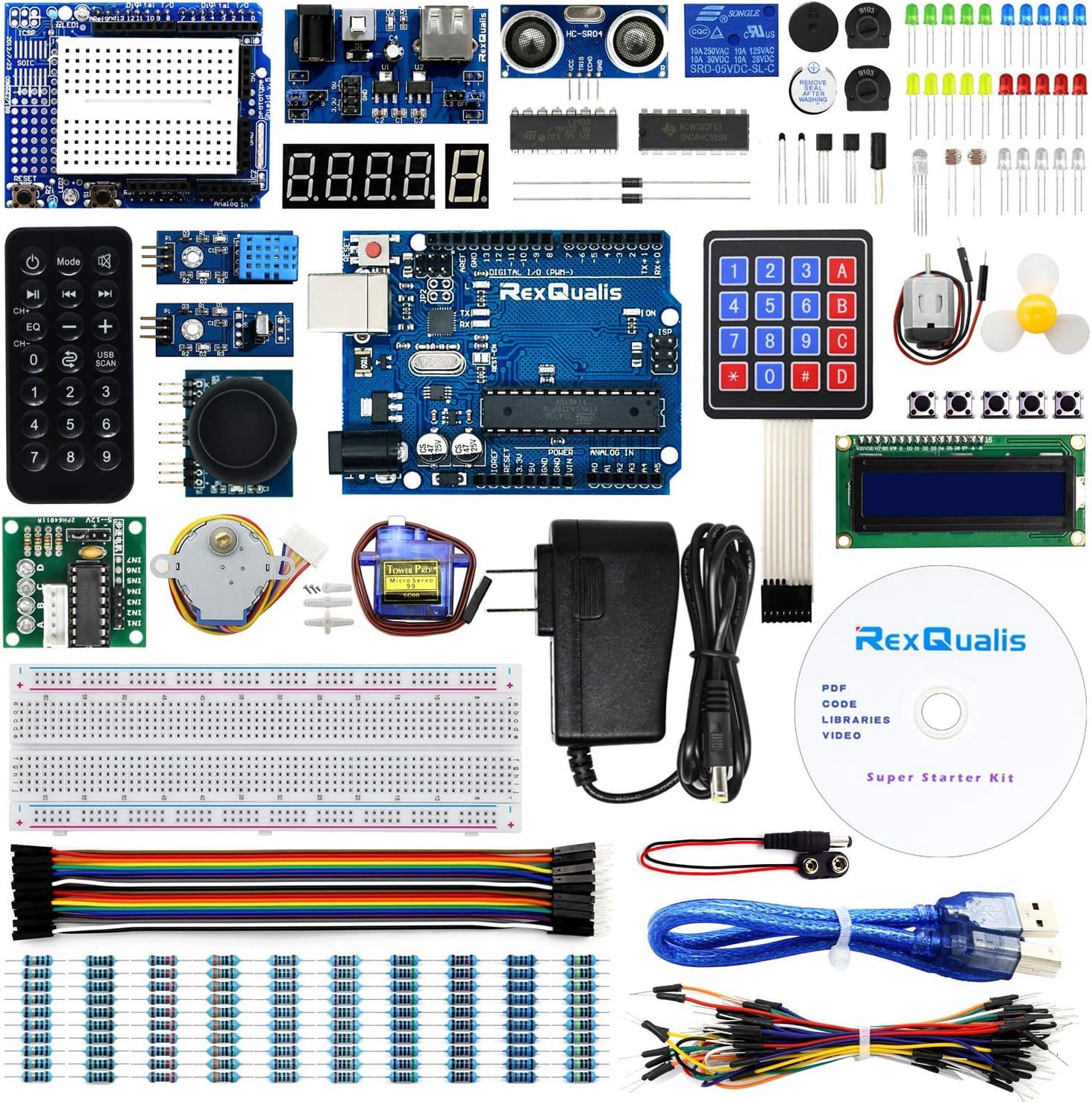
REXQualis Super Starter Kit based on Arduino UNO R3 with Tutorial and Controller Board Compatible with Arduino IDE
REXQualis
- The most economical kit comes with everything compatible with Arduino to starting programming for beginners .
- This is the upgraded starter kits come with a 9V 1A Power Adapter (At least $5.99 on amazon) to replace a 9V Battery , and the Lcd1602 module come with pin header(not need to be soldered by yourself).
- Include High Quality Base Board base on Arduino UNO R3 compatible with Arduino IED and Sensors, Servo, Motor, ULN2003 driver board, lcds, etc.
- Free PDF Tutorial and Datasheet are available to download from our official website or you can contact our customer service.
- All of the Components and Integrated Circuits are individually packaged and labeled, and packing in a plastic box which is bigger enough for you.
User questions & answers
| Question: | what kinds of electronic projects can i build with this kit |
| Answer: | I've been in computers 40+ years; this is a great package to teach coding. I'm teaching high schools kids. Package, and also on the web, are great short simple examples. Only think I've added is a card with 4 relays. We are programming a model railroad; important to 'see' what your code is doing. Well spent $40. Great Christmas present for 15+ year olds. |
| Question: | Would the 9v 1a adapter come eu according to my shipping address |
| Answer: | Dear, Sorry, we are unable to provide different plug specifications according to the address. Currently, the plugs included in this kit are US-compliant. |
| Question: | What size are the resistors |
| Answer: | 10 100 220 330 1k 2k 5k 10k 100k 1meg you get ten each of these. This is a great kit. only thing I added was four relays. |
| Question: | Can you use the arduino software with this |
| Answer: | Yes, it comes with an arduino UNO board. You just need to download and install the arduino IDE on your computer and you're good to go. |
Product features
REXQualis Super Starter Kit help everyone easy-to-get started with programming and robotics.
- REXQualis Super Starter Kit include a large number of components and sensors, it suitable for everyone to learn electronics and programming. we provide a detailed tutorial, introducing the basic setting compatible with Arduino IDE, the working principles of the sensors and the simple program to enable the microcontroller board to control the sensors.
- For novice users, even if you don't have any electronics knowledge, we provide a detailed and easy-to-understand tutorials, just follow our tutorial and step by step, you will find that it is more fun than you ever expected.
- For advanced users, like lab engineers, teachers , students and makers, use it to build low cost scientific instruments, to prove chemistry and physics principles, or to get started with programming and robotics.
- It’s also a good choice and perfect gift for your family or kids who are obsessed with electronics, programming or robotics, so that you can study and grow together.
LCD1602 Display Module
In this project , you will learn how to connect LCD Display to microcontroller board and display what we type. In addition, with the Potentiometer we can control the brightness of the screen.
LCD1602 module is a display that has an LED backlight and can display two rows with up to 16 characters on each row. You can see the rectangles for each character on the display and the pixels that make up each character. The display is just white on blue and is intended for showing text.
REXQualis LCD1602 Module come with pin header, not need to be soldered by yourself.Then you can easy to Lining up the display with the top of the breadboard helps to identify its pins.
Control Stepper Motor by IR
In this project, you will learn a fun and easy way to control a stepper motor from a distance using an IR remote control.
The 28BYJ-48 is a small 5 volt geared stepping motors which are apparently widely used to control things like automated blinds, A/C units. And it come with a ULN2003 stepper motor driver board, allows you to easily control the 28BYJ-48 stepper motor from a microcontroller.
The IR sensor is connected to the microcontroller board directly since it uses almost no power.When you are fully connected, you can control the stepping motor through IR remote.
DC Motor with L293D and Relay
In this project you will learn how to control a small DC motor by microcontroller board with using a L293D transistor and Relay.
L293D transistor is a very practical chip that can independently control two DC motors. In this experiment, just half of the chip is used. Since most pins on the right side of the chip are used to control the second motor, they will not be used here.
Relays are generally used to switch smaller currents in a control circuit and do not usually control power consuming devices except for small motors and Solenoids that draw low amps. Nonetheless, relays can "control" larger voltages and amperes by having an amplifying effect because a small voltage applied to a relays coil can result in a large voltage being switched by the contacts.
Component listing:

3D Printer CNC Controller Kit with for ArduinoIDE, Longruner GRBL CNC Shield Board+RAMPS 1.4 Mechanical Switch Endstop DRV8825 A4988 Stepper Motor Driver Nema 17 Stepper Motor LKB02
Longruner
User questions & answers
| Question: | The drv8825 seem to have no pad for measuring vref like the polulo version has. where can i measure vref |
| Answer: | If I remember correct you measure it from the adjustment screw itself. |
| Question: | Can this be used with Nema 23 425 oz/in steppers |
| Answer: | Yes |
| Question: | Hello, could anyone help with some simple code? I am looking to simple say - this motor rotate this much then stop |
| Answer: | Here is the test code for testing 3 motor positive reversals: https://mega.nz/#F!XENxlahT!40uX7JxNvTsCdGtXRg3J1Q By adjusting the number of pulses, you can determine how large the angle is. One pulse is 1.8 degrees and the test code is 200 pulses. You can adjust this to adjust the angle of rotation, such as 2 laps is 400. Any question please feel free to contact with us. [email protected] |
| Question: | What else do I need to use this for a cnc |
| Answer: | You need the machine frame and table, some type of head or spindle, whether a 3d extruder or cutting spindle. A computer, software and drive mechanisms such as belts or lead screws. Some combination of patience and skill to put it all together. |
Product features
Nema 17 stepper motor 1.7 A
3 x Nema 17 stepper motor 1.7 A (with bracket and screw) + 3 x Nema 17 Stepper Motor Mounting Bracket
Model No.:17HD48002H-22B Step Angle: 1.8 deg Holding Torque: 59Ncm(84 oz.in) Rated Current/phase: 1.7A Frame Size: 41 x 41mm Body Length: 47mm Shaft Diameter: 5mm Shaft Length: 22mm Weight: 380g
for Board + 1 x 1.5m USB cable
MCU: ATmega328
USB interface: ATmega16U2 Operating voltage: 5V Digital I/O pins: 14 (including 6 with PWM capability) Analog input pins: 6 I-I/O pin output current: 40mA max 3.3V output current: 150mA max Flash memory: 32 kB (0.5kB used by bootloader - included) Static RAM (SRAM): 2 kB EEPROM: 1 kB Clock speed: 16MHz
DRV8825 Stepper Motor Driver
4 x DRV8825 Stepper Motor Driver + 4 x Aluminum heat sink w/ 3M tape backing
Upgraded from A4988, 2.5 A max current/phase.
CNC Shield Board
Latest CNC Shield Version 3.0.
GRBL 0.9 compatible.
4-Axis support (X, Y, Z , A-Can duplicate X,Y,Z or do a full 4th axis with custom firmware using pins D12 and D13).
Support 6pcs ends stop for each axis.
Coolant enable.
Compatible with A4988 or DRV8825 stepper driver.
Runs on 12-36V DC.

KeeYees L298N Motor Drive Controller Board Stepper Motor Control Module Dual H-Bridge with DC Motor and Smart Car Wheel Compatible with Arduino
Product description
Specification:
Motor Drive Module
Operating mode: H-bridge driver (dual)
Chip: L298N
Logic voltage: 5V
Logic current 0mA-36mA
Drive voltage: 5V-35V
Drive current: 2A (MAX single bridge)
Maximum power: 25W
Dimensions: 43x43x27mm
Note:
General Application:
When your driver is 7V-12V (Marked as 12V Input), you can use the on-board 5V logic supply.
When using the on-board 5V power supply, do not input voltage at interface 5V Input, but it can
draw 5V voltage for external use.
Unconventional application of high-voltage drive:
When the driving voltage is higher than 12V, less than or equal to 24V. First, the onboard 5V
output enabled jumper cap must be removed, and then connect the 5V external voltage to the
5V Input interface to power the L298N internal logic circuit.
DC Motor
Operating Voltage: 3V ~ 6V DC
Reduction ratio: 1:48
When the voltage is 6V:
No-load current: ≤200mA
No-load speed: 200±10%rpm
When the voltage 3V:
No-load current: ≤150mA
No-load speed: 90±10%rpm
Product List:
4 x Smart Car Wheel
4 x DC Motor
2 x L298N Motor Drive Controller Board
20 x 20CM Jumer Wire female to female
20 x 20CM Jumer Wire Male to Male
20 x 20CM Jumer Wire Male to Female
KeeYees: Best choice in various Electronic Modules & Components, DIY Parts and Tools to
support your work and design challenges from Home, School to Industrial applications!
- This is a good parts kit for an Arduino and raspberry pi based RC car project. It not only comes with 4pcs wheels and motors, but also 2pcs motor drive modules and 60pcs jumper wires, which are very useful accessories for your project.
- Motor Drive Controller: L298N used as the main driver chip. It has the strong driving ability, low calorific value and strong anti-interference ability.
- TT Motor: The motor is a two-axis motor with a reduction ratio of 1:48, which has strong anti-interference ability.
- Smart Car Wheels: The wheels are made of high-strength plastic and the tires are made of durable black rubber.
- To avoid damage the voltage stabilizing chip of Motor Drive Module, please use an external 5V logic supply when using more than 12V driving voltage.
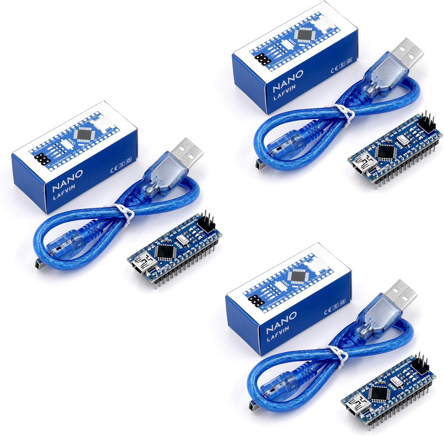
Nano V3.0, Nano Board ATmega328P 5V 16M Micro-Controller Board Compatible with Arduino IDE (Nano x 3 with USB Cable)
Product description
Specification:
CH340G Replace FT232RL.
Operating Voltage(logic level): 5V.
8 analog inputs ports:A0 ~ A7.
14 Digital input / output ports:TX,RX,D2 ~ D13.
6 PWM ports:D3, D5, D6, D9, D10, D11.
1 pairs of TTL level serial transceiver ports RX / TX.
Support USB download and Power.
Support for external 5V ~ 12V DC power supply.
Support power supply by 9V battery.
Support ISP download.
Package including:
3 x LAFVIN Nano V3.0 with ATMEGA328P Module
3 x USB Cable
- Original ATmega328P CH340 chip is used. Improved new version CH340G Replace FT232RL.
- LAFVIN Nano V3.0 card is 100% compatible with the Nano card, and fully compatible with Windows, Mac and Linux operating system.
- Works the same as original Nano, runs perfectly on programming software.
- Using Atmel Atmega328P-AU MCU, Support ISP download; Support USB download and Power.
- LAFVIN Nano CH340 controller is a compact board similar to the R3 board, smaller and breadboard-friendly than Diecimila.
User questions & answers
| Question: | What voltage battery for these |
| Answer: | Variable. Can connect to USB via mini-USB connecor. Higher voltages up to 9V can connect to power pins |
| Question: | Do these boards come assembled or will the pins need to be soldered upon arrival |
| Answer: | they come fully assembled |
| Question: | I am unable to upload a sketch to all 3 boards.. even when switching to old bootloader, are they bad boards |
| Answer: | I purchased 2 sets of 3ea LAFVIN boards assembled with headers and USB cables August 2020. Using Arduino IDE 1.8.5 could not upload sketch to Nano. Changed Tools->Board=Arduino/Genuino Uno and was able to upload sketch. The Nano thinks it is a Uno. I do not know if there are any other differences. |
| Question: | Does anyone know how to update the bootloader on these boards |
| Answer: | use the ATmega328p (old Bootloader) setting. works good for me |
Product features
LAFVIN Nano V3.0, Nano Board
LAFVIN nano ch340 controller is a small, complete board based on the ATmega328.It is a smallest, complete, and breadboard friendly. It has everything that Diecimila/Duemilanove has (electrically) with more analog input pins and onboard +5V AREF jumper. Physically, it is missing power jack. The Nano is automatically sense and switch to the higher potential source of power, there is no need for the power select jumper.
Specification:
CH340G Replace FT232RL.
Operating Voltage(logic level): 5V.
8 analog inputs ports:A0 ~ A7.
14 Digital input / output ports:TX,RX,D2 ~ D13.
6 PWM ports:D3, D5, D6, D9, D10, D11.
1 pairs of TTL level serial transceiver ports RX / TX.
Support USB download and Power.
Support for external 5V ~ 12V DC power supply.
Support power supply by 9V battery.
Support ISP download.
Mini USB
The LAFVIN Nano can be powered via the Mini-B USB connection.
Microcontroller
ATmega328P – 8 bit AVR family microcontroller.
Reset button
The button can resets the microcontroller.
FTDI USB Chip
The FTDI FT232RL chip on the Nano is only powered if the board is being powered over USB.

KEYESTUDIO 16-Channel 12-bit Servo Motor Driver Board I2C Interface for Arduino R3 Controller
Product description
Specification
1.I2C input, to control 16-channel PWM output
2.Servo power supply independent V + input up to 6V
3.Logic signal and logic power independent output 3-5v
4.Frequency of 40-1000Hz
5.Number of channels: 16-channel
6.Resolution: 12-bit
- This expansion board can directly stack on the controller R3 board and can drive up to 16 servos
- Uses I2C input, just occupy A4 and A5 interface on the control board
- Contains PCB double sided holes, can direct to solder with components to build up prototyping circuits
- Servo power supply independent V + input up to 6V
- How to use: Search for "keyestudio wiki KS0258" in Google Chrome to get the wiki online tutorial for this product.
User questions & answers
| Question: | Does this come assembled? It does not say. Is any assembly required |
| Answer: | Yes this product comes fully assembled. All you have to do is plug it into an Arduino uno and your all set. |
| Question: | How many amps per channel |
| Answer: | I can't help you. I bought it along with a bunch of other parts for my son who is building a robot. |

Traffic Light Controller ARDUINO Based Sequencer AC Voltage Solid Sate Relay SSR (Unlimited Modes/Options Programmable) 100V-240VAC 50HZ-60HZ 3 Channel RED Green Yellow RYG Built-in Indicator LEDs
Product description
CAUTIONS
1 USER NEEDS TO KNOW BASIC PROGRAMMING LANGUAGE
2 WE DO NOT SHIP MANUAL ALL MANUALS IN DESCRIPTION AND PRODUCT BULLTES AREA. PLEASE SEE LINKS BEFORE YOU BUY
3CH Traffic Light Controller, programmable board ARDUINO BASED
Our Traffic Light Controller is the perfect solution for all of your traffic signal needs. Accepting standard 120VAC and 240VAC line voltage, this controller provides 500 Watts per channel and will drive full-sized LED and incandescent traffic lights (this includes all household incandescent and LED bulbs). This board is based with the latest solid state relays. Solid state relays technology means quiet, effortless switching for many years.
Now is very simple programming all traffic lights timings with arduino software. USB-UART bridge is based on popular CH340G chip. This board is already programmed with simple traffic lights demo code. Also, all others demo codes are provided below.
What need user to start working with this board?
1.Download and install CH340G USB driver
2.Download and install arduino programming software from webpage
3.Connect device to the computer via usb cable
4.And upload demo or user written sketches to the board
Device specification:
PCB board dimension – 70mm x 100mm , color green
PCB Board Material - 1.6 mm FR-4, with solder mask & silk screen
Input Connector - 14-26AWG, 250VAC @ 16A screw terminals
Output Connectors - 14-26AWG, 250VAC @ 16A screw terminals
Safety fuse - 8A
https://youtu.be/7hMyxDv9wyU
CH340G Diver installation
https://drive.google.com/open?id=1OrJOsWfEK_4dQDD5T9-04LrOq2ZWu8OC
Many Arduino Sample Code is here
https://drive.google.com/drive/folders/1L5FXpbV15tA1YiWeLMXzIEcGCkssnyF7
How to install demo code (get one of the demo code from above link) and use below manual
https://drive.google.com/open?id=1L_vngOVdCaDGYUuDo2wi3i_f1dyo_Qkg
More Detailed Video https://youtu.be/lqjk7FRlzyM
- 🚦 This device requires basic ARDUINO programming knowledge. THE IDEAL UNIVERSAL TRAFFIC LIGHT CONTROLLER. Wide input AC voltage range 100-240VAC / 50HZ 60HZ
- 🚦Min output load 5W and max 500W per channel. Independent outputs channels for operating LEDs or incandescent lamps. It can be used as 3 Channel or 2 Channel for RAILROADS or 1 Channel depends on your application.
- 🚦NOT for fluorescent bulbs!!!
- 🚦 Output RX-TX pins for 5.0V and 3.3V logic levels. Specially made for easy Bluetooth, WI-FI or any other serial protocol modules
- 🚦 3 channel traffic light controller is based on uno bootloader with ATMEGA328P microcontroller. USB-UART bridge is based on popular CH340G chip. 📺 Watch video youtube.com/watch?v=LQR3SrBOcko 🎬
User questions & answers
| Question: | I wish to hang a traffic light in my shop will it auto. sequence through changes with this board with no addtl programming? approx 10-15 sec changes |
| Answer: | Hi I just prepared a YouTube video. I tried to explain every detail of how to program this ARDUINO based device. Please see below link to find more information. Simply what you need to do is changing sketch values on example to what you need. For example if it says 1000 in code, it means 1 second, if you want to make 15 seconds, you just need to write there 15000 and upload code to your device. That is it. Of course you need have on hand mini usb cable and you need to install your computer FREE Arduino program from arduino.cc YouTube Link is youtube.com/watch?v=LQR3SrBOcko Thanks for purchasing and support. With your help, we will build better products for you. |
| Question: | Have no idea how how to program this! You say free software from the website, what website? Does anybody, anywhere show step by step instructions |
| Answer: | Hi Thank you for your interest about our product. As we stated on our product listing this is Ardunio based product. So you can download arduino from www.arduino.cc . We tried make also pdf documents and some videos to show our user how to program this device. You can find more detailed video on this link https://youtu.be/lqjk7FRlzyM also all the documents and videos listed under the product description on amazon https://www.amazon.com/dp/B07JD3ZH3M . This Arduino based is developed for unlimited mode option. We have another product with asin code B083PPD44 on amazon. This product, you do need to know any programming language to program. there is a knob on the product and you can select one of the best option/mode for your application need. you are welcome to ask any other question you may Thank you so much again |
| Question: | Where do i get the app |
| Answer: | Hi I just prepared a YouTube video. I tried to explain every detail of how to program this ARDUINO based device. Please see below link to find more information. Simply what you need to do is changing sketch values on example to what you need. For example if it says 1000 in code, it means 1 second, if you want to make 15 seconds, you just need to write there 15000 and upload code to your device. That is it. Of course you need have on hand mini usb cable and you need to install your computer FREE Arduino program from arduino.cc YouTube Link is youtube.com/watch?v=LQR3SrBOcko Thanks for purchasing and support. With your help, we will build better products for you. |
| Question: | Will this operate an incandescent 120v traffic light directly? Or will it only control the relays supplying the voltage |
| Answer: | Mine is controlling an LED light but it is rated at 500 watts per channel which is more than enough to operate a 120 volt incandescent light. |
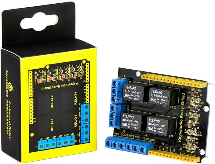
KEYESTUDIO 4 Channel Relay Shield 5V for Arduino Controller R3 ARM PIC AVR STM32 Raspberry Pi HIGH Level Trigger Relay Module Expansion Board
Product description
WHY CHOOSE KEYESTUDIO!
1.EXCELLENT QUALITY
solder is very clean, everything is aligned nicely, all boards are well packed after function,voltage, current testing
2.COOL YELLOW BLACK DESIGN
The yellow trim is definitely a departure from the standard, dull, black boards, and the yellow silk screen on black mask really pops, making it easy to read the pin labels
3. REALLY SAFE
This board is made from environmental-friendly components and materials, as well as environmental-friendly production technology
Features:
Channel: 4 channel
The relay shield is 5V active HIGH
Contact capacity: AC120V / 3A ; DC24V/3A
Onboard LED indicator for relay output status
Indicator: 4 LEDs are red when the relay is driven high, the corresponding indicator will light up.
Standard interface can be directly plugged into microcontrollers.
Fully compatible with controller R3 board
Power Interface: 5V DC power interface
Indicator LED onboard for Relay output status
Relay 1 (I/O pin 4) is connected to a terminal J4; Relay 2 (I/O pin 5) is connected to J3; Relay 4 is connected to J1.
Be able to control various appliances and other equipment with large current.
3 M3 screw positioning holes for easy installation
- It integrates 4-channel 5V relay module, and is fully compatible with R3 control board.
- The 4-channel relay module shield is active at HIGH level.
- Relay Terminals: high-power, high-current high voltage can be connected to the device.
- Separately connect the 4-channel relay to digital port 4, 5, 6, 7 on the R3 control board, then through controlling output HIGH or LOW to control the relay on and off.
- How to use: search for "keyestudio wiki ks0251" in Google Chrome to get the wiki online tutorial for this product.

Qunqi L298N Motor Drive Controller Board Module Dual H Bridge DC Stepper For Arduino
Product description
Specification:
Chip: L298N
Logic voltage: 5V
Logic current 0mA-36mA
Storage Temperature: -20 ℃ to ℃ to +135
Operating mode: H-bridge driver (dual)
Drive voltage: 5V-35V
Drive current: 2A (MAX single bridge)
Maximum power: 25W
Dimensions: 43x43x27mm
Package include:
1x L298N Module
Note:
This module has a built-in 5v power supply, when the driving voltage is 7v-35v, this supply is suitable for power supply
DO NOT input voltage to +5v supply interface, however ledding out 5v for external use is available.
When ENA enable IN1 IN2 control OUT1 OUT2
When ENB enable IN3 IN4 control OUT3 OUT4
- Dual-channel H-bridge driver working mode creates higher working efficiency,L298N as main chip.Can drive one 2-phase stepper motor, one 4-phase stepper motor or two DC motors.
- To avoid damage the voltage stabilizing chip, please use an external 5V logic supply when using more than 12V driving voltage
- Use large-capacity filter capacitors and diode with freewheeling protection function, increasing reliability
- High working power to 35v,large current can reach 3A MAX and continue current is 2A, power to 25w.
- Large capacity filter capacitance,afterflow protection diode, more stable and reliable.
User questions & answers
| Question: | Is there a way for me to detect a stall using this driver |
| Answer: | No, there is no feedback from the motor to the driver. Possibly monitor the current used by the motor with a Hall Effect transducer and, if it exceeds a certain value, consider it stalled. |
| Question: | I lose the voltage from 10v to 4.5v, as soon as I connect to motor controller. Any idea why it is happening and how to correct it |
| Answer: | I need a bit of context for your question. are you using a microcontroller with the L298? How many motors are you using? do you have a separate power supply for said source of controls? Are you using an arduino? |
| Question: | Can you use this with the Arduino Stepper.h library to run a 5V stepper motor? When I use it at the full 12V it heats up my motor like crazy |
| Answer: | 5V is the limit. 12V will burn up the motor. |
| Question: | What are those blue connectors for? Can I see a connecting diagram or instructions of some sort |
| Answer: | The blue terminal blocks are for power connections. The 3-term block is for supply voltage, ground, and +5V out from on-board regulator. Each 2-term block is for a power circuit to a motor (voltage is same as supply). A search online for "l298n driver module" images gives a lot of useful connection diagrams. ST Microelectronics provides good technical documentation for the L298 IC, itself, which describes the power limitations. |
Product features
Qunqi L298N Motor Drive Controller Board Module Dual H Bridge DC Stepper For Arduino
- Specification:
- Chip: L298N
- Logic voltage: 5V
- Logic current 0mA-36mA
- Storage Temperature: -20 ℃ to ℃ to +135
- Operating mode: H-bridge driver (dual)
- Drive voltage: 5V-35V
- Drive current: 2A (MAX single bridge)
- Maximum power: 25W
- Dimensions: 43x43x27mm
Note:
Package include:
Detail Picture:
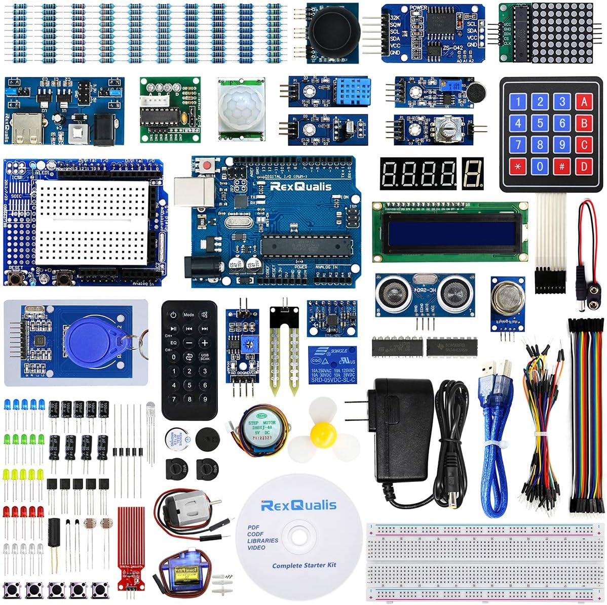
REXQualis Complete Starter Kit based on Arduino UNO R3 w/Detailed Tutorial and Controller Board Compatible with Arduino IDE
REXQualis
- REXQualis complete starter kit base on Arduino UNO R3 comes with more than 200pcs components, 67 kinds of components and sensors module.
- LCD1602 Module,MPU-6050 Module and RC522 RFID Module come with pin header, Motors come with wires, not need to solder by yourself.
- Include High Quality Base Board base on Arduino UNO R3 and Sensors, 100% compatible with Arduino IDE.
- Free PDF Tutorial and Datasheet are available to download from our official website or you can contact our customer service.
- All of the Components and Integrated Circuits are individually packaged and labeled,including some nice small boxs to keep the widget such as LED, IC, buttons, diodes, etc
User questions & answers
| Question: | What gauge are the wires that come with this kit |
| Answer: | 9V / 1A |
| Question: | Does it ship with batteries included |
| Answer: | The Remote and Real Time Clock Module is come with CR2 batteries. |
| Question: | Cual es el funcionamiento de este producto |
| Answer: | Hello, is the program running on the Arduino ide through the arduino board, and the function is reflected through the connected module。 |
| Question: | What is it |
| Answer: | This is an stating kit, you can work on this as a testing environment. |
Product features
REXQualis Complete Starter Kit help everyone easy-to-get started with programming and robotics.
- REXQualis Complete Starter Kit include a large number of components and sensors, it suitable for everyone to learn electronics and programming. we provide a detailed tutorial, introducing the basic setting compatible with Arduino IDE, the working principles of the sensors and the simple program to enable the microcontroller board to control the sensors.
- For novice users, even if you don't have any electronics knowledge, we provide a detailed and easy-to-understand tutorials, just follow our tutorial and step by step, you will find that it is more fun than you ever expected.
- For advanced users, like lab engineers, teachers , students and makers, use it to build low cost scientific instruments, to prove chemistry and physics principles, or to get started with programming and robotics.
- It’s also a good choice and perfect gift for your family or kids who are obsessed with electronics, programming or robotics, so that you can study and grow together.
LCD1602 Display Module
In this project , you will learn how to connect LCD Display to microcontroller board and display what we type. In addition, with the Potentiometer we can control the brightness of the screen.
LCD1602 module is a display that has an LED backlight and can display two rows with up to 16 characters on each row. You can see the rectangles for each character on the display and the pixels that make up each character. The display is just white on blue and is intended for showing text.
REXQualis LCD1602 Module come with pin header, not need to be soldered by yourself. Then you can easy to Lining up the display with the top of the breadboard helps to identify its pins.
Control Stepper Motor by IR
In this project, you will learn a fun and easy way to control a stepper motor from a distance using an IR remote control.
The 28BYJ-48 is a small 5 volt geared stepping motors which are apparently widely used to control things like automated blinds, A/C units. And it come with a ULN2003 stepper motor driver board, allows you to easily control the 28BYJ-48 stepper motor from a microcontroller.
The IR sensor is connected to the microcontroller board directly since it uses almost no power.When you are fully connected, you can control the stepping motor through IR remote.
Soil Moisture Sensor Module
In this project, you will understand how you can use the soil moisture sensor in your projects. The soil moisture sensor or the hygrometer is usually used to detect the humidity of the soil. So, it is perfect to build an automatic watering system or to monitor the soil moisture of your plants. The voltage that the sensor outputs changes accordingly to the water content in the soil.When the soil is:
- Wet: the output voltage decreases
- Dry: the output voltage increases
Component listing:

SUBALIGU L298P DC Motor Drive Module Motor Drive Shield H-Bridge Drive Expansion Board High-Power DC Stepper Motor Controller Compatible with A-rduino
Product description
Technical Specifications:
1. Logical part of the input voltage VD: 5V
2. Driven part of the input voltage VS: VIN Input 6.5 ~ 12V, PWRIN 4.8 ~ 35V input
3. Logical part of the work current Iss: <36mA
4. Driven part of the operating current Io: <2A
5. Maximum power dissipation: 25W (T = 75 Celsius)
6. control signal input level: High 2.3V low -0.3V
7. Working temperature: -25 + 130 Celsius
8. Hardware interface: 5.0mm pitch terminal
9. Belt clip and can be controlled via front row access signal
10. Drive Type: Dual power H-bridge driver
11. Pin occupancy: D4 ~ D7 direct drive motor
12. Supports PWM / PLL mode motor speed control
13. Size: 68 * 53mm
Packing included:
1 x L298P Motor Driver Module
- Driven part of the input voltage VS: VIN Input 6.5 ~ 12V, PWRIN 4.8 ~ 35V input.
- The L298P shield DC motor driver has PWM speed control mode; dual high-power H-bridge driver.
- Supports PWM / PLL mode motor speed control
- Stack design can be directly plugged into the A-rduino, easier to use.
- Adopt dedicated high-power motor driver chip L298P which can directly drive two DC motors with drive current up to 2A.

Joystick PS2 Module - SunFounder DC 5V Joystick Breakout Module Game Controller for Arduino and Raspberry Pi
Product description
Introduction
Application
The Joystick module is usually used to be applied to convenient control of objects (like a two-degree of freedom servo mount) to move in a two-dimensional space. With power light and indicator of digital signal output. It can be used in the remote controller for many robot projects
Component List
- 1 x Joystick PS2 module
- 1 x 5-Pin anti-reverse jumper wire
- Works with Arduino and Raspberry Pi
- Game joystick PS2 module suits for Arduino PS2 , connects to two analog outputs, the robot is at your commands with X,Y control, and one of digital output (Z).
- The cross rocker is a bidirectional 10k resistor; its resistance changes with different directions. Push the joystick towards different directions and the voltage read increases or decreases
- Press it down, then the output is low level and the corresponding LED lights up; otherwise it stays off.
User questions & answers
| Question: | Will this work with an easy 5 pin connection with an arcade USB encoder? or would i need to repin/arrange the pins for the arcade board |
| Answer: | Hi, about this question, could you please contact us via [email protected], so that we can help you better, thanks. |

Arducam 1602 16x2 LCD Display Module Based on HD44780 Controller Character White on Blue with Backlight for Arduino, Raspberry Pi Pico
Arducam
Product description
Feature:
Wide viewing angle and high contrast
Commonly used in: copiers, fax machines, laser printers,industrial test equipment, networking equipment such as routers and storage devices
Voltage: 5V DC
LCD display type: Characters
Module dimension: 80mm x 35mm x 11mm
Packing included:
1pcs 1602 16x2 LCD Display Module
FTP support for datasheets
User questions & answers
| Question: | Does this LCD come in a version supporting black on white text color |
| Answer: | Dear sir, We are sorry to tell you that we have not black on white color LCD now. If you have any issues about the product, please feel free to let us know and we will try our best to solve it. Best regards, Linda from Arducam Support Team |
| Question: | Title says that it is for arduino and raspberry pi pico. but pico uses 3v and this unit uses 5v. is it compatible? can it be used with pico |
| Answer: | You need a level shifter like https://www.amazon.com/gp/product/B074M8TM81 That lcd module uses about 6 or 8 lines so you would need to use 2 or three of this type level shifter. |
| Question: | I am unable to write to the second line. I think it shoud start at 40. Does it |
| Answer: | Perhaps, you can add a 0x40 to the 2nd line, you can refer to the next code.#include #define uchar unsigned char #define uint unsigned int sbit lcden=P3^2; //enable com sbit lcdrs=P3^0; //Data command options sbit rw=P3^1; uchar code table="xian shi 1"; //Type the charactersuchar code table1="xian shi 2"; //Type the charactersuchar num=0; void delay(uint z) { uint x,y; for(x=z;x>0;x--) for(y=110;y>0;y--); } void write_com(uchar com)//According to the sequence diagram write instruction program{ lcdrs=0; rw=0; P1=com; delay(5); lcden=1; delay(5); lcden=0; } void write_data(uchar date)//According to the sequence diagram write data program{ lcdrs=1; rw=0; P1=date; delay(5); lcden=1; delay(5); lcden=0; } void init() { lcden=0; //Can make the low level write_com(0x38); /*Display mode setting 00111000 set 16 * 2 5 * 7 lattice 8 bits of data interface*/ write_com(0x0f); /*Display switch and the cursor 00001 DCB Settings D = 1, open display D = 0, turn off the display C = 1, display the cursor C = 0, do not display the cursor B = 1, the cursor blink B = 0, the cursor is not flashing*/ write_com(0x06);//Address pointer + 1 + 1, and the cursor automatically write character screen do not move write_com(0X01); write_com(0X80); } void main() { init(); for(num=0;num { write_data(tablenum); delay(50); } write_com(0X80+0x40); for(num=0;num { write_data(table1num); delay(50); } while(1); } For more information, please visit: http://www.uctronics.com/Amazon/Arducam_C0048_1602.pdf |
| Question: | Where can I find a bezel/faceplate to fit this display? I want to snap it onto the perimeter to finish my project |
| Answer: | I found some plastic face plates that were apparently die cut for this size display. They are designed to be bolted or glued over the panel opening housing the display. If I remember correctly, they are available in different colors and sizes. I bought a dozen of them and I am happy with the results. They do not snap onto the perimeter of the display. I found them by Google searching the internet. I wish I could give you the URL but do not have it handy. |
Latest Reviews
View all
Suave Natural Shampoos
- Updated: 19.04.2023
- Read reviews
Touchupdirect Pens
- Updated: 30.01.2023
- Read reviews

Umbrella Ninja Swords
- Updated: 23.05.2023
- Read reviews

Mac Sports Outdoor Sport Umbrellas
- Updated: 26.02.2023
- Read reviews

Man Osts
- Updated: 09.05.2023
- Read reviews